An exposure hand switch model designation is a configuration label, not a quality ranking. The letter-and-number code separates models by stage structure, connection form and housing or trigger variant. A real advantage appears when one of those configuration groups matches the examination workflow and the exposure interface of a specific machine; a longer code or a higher position in a product list carries no technical meaning. The written specification sheet, not the designation, is the document that defines what a delivered unit contains.
WhatsApp: +86 19062611512. Email: admin@newheek.cn
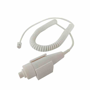
A hand switch designation on the public product pages is built from three readable parts. The leading letter identifies the product line. The numeric segment identifies the configuration family, which is where stage count and connection form are grouped. A trailing letter marks a variant inside that family, commonly a different trigger mechanism, shell finish or colour option.
That structure is useful for filing and for ordering, and it is easy to over-read. A suffix does not indicate a newer generation, a higher rating or an upgraded component set; it indicates a variation. Two units from the same family can differ in cord core count, plug type or shell colour while sharing the same stage logic. Conversely, two designations that look unrelated can serve the same workflow once the interface is confirmed in writing. The designation answers which configuration family a unit belongs to. The specification sheet answers what that unit does.
The six hand switch models listed on the in-stock product pages fall into three stage groups and two connection groups. The table below is a qualitative grouping; every electrical, dimensional and lifetime figure is deliberately absent because those values belong to the written sheet that accompanies a quotation.
| Designation | Stage structure | Connection form | Housing and trigger feature | Workflow the family fits |
|---|---|---|---|---|
| L01 | Two-stage | Corded, coiled cord | Mechanical plunger drive, plain shell | Fixed DR room, general radiography |
| L01A | Two-stage | Corded, coiled cord | Spring-strip trigger, smooth shell | High-frequency general radiography |
| L07A | Two-stage | Corded, coiled cord | Mechanical switch, spring-strip trigger | General DR and veterinary imaging |
| L08A | Two-stage | Corded, coiled cord | Two-tone shell options, light and dark | Multi-room sites with colour-coded accessories |
| L06A | Single-stage | DR-dedicated configuration as labelled on the product page | Sealed, low-noise construction | Short, fixed-position acquisition sequences |
| L03 | Three-stage | Cordless handset with a paired receiver | Additional control for the collimator lamp | Positioning work with light-field checks away from the console |
One caution belongs beside this table. The public product pages and the internal product data do not describe the connection form of every designation in identical terms; one DR-dedicated model is labelled with a cordless description in one place and with a corded construction in another. The grouping above therefore states the configuration family and the workflow, and leaves the connection form to written confirmation. A designation is not a substitute for that confirmation.
The L01, L01A, L07A and L08A families share one advantage that matters more than any component detail: a two-stage sequence. The first step closes the prepare circuit and brings the generator into a ready state; the second step closes the exposure circuit while the first remains held. Releasing the button opens both circuits. The gap between the two steps is a decision point. If positioning has shifted, if a patient or an animal has moved, or if a cassette and detector are not yet in place, the exposure has not started and the sequence can be abandoned without producing an image.
That window is a workflow advantage rather than a specification claim. A room with frequent repositioning, a veterinary table with an uncooperative patient, or a mixed caseload gains more from the prepare stage than a room with a fixed, repeatable setup. The practical boundary is equally plain: the prepare signal has to be understood by the generator. Stage logic is an interface agreement between hand switch and machine, and it is confirmed against the machine’s exposure input documentation before an order is placed.
Within the two-stage group, the variants address handling rather than imaging. A mechanical plunger drive gives a direct, consistent travel from button to switch element. A spring-strip trigger changes the feel of that travel and suits operators who press the same control across a long list of examinations. The smooth or contoured shell changes grip and cleaning behaviour. None of these variants changes the exposure itself; their advantage is that a high-frequency control stays predictable in the hand over a working day.
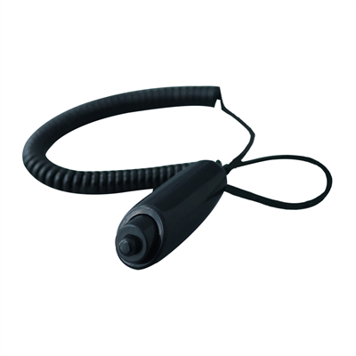
The L03 family adds a third control position for the collimator lamp. Its advantage is spatial rather than electrical. Field-light alignment is part of positioning, and positioning happens at the table or the stand, not at the console. A control that carries the lamp function lets the same operator set the light field and then proceed to the prepare and exposure stages without changing position or calling a second person to the console. Rooms that perform a lot of field-light adjustments gain a shorter, quieter positioning routine.
The cordless handset with a paired receiver adds a second advantage to the same family: operating distance. A cordless control removes the cord from the floor around a table and allows the operator to stand where the room layout and the local radiation protection plan require. The corresponding obligations are equally concrete. A receiver has to be mounted, paired and powered; a handset has a battery state that belongs in a room checklist; and the response of a radio link has to be verified in the actual room, among the actual equipment, before the unit enters clinical use. A cordless model is not an upgrade that removes maintenance; it trades cord maintenance for battery and pairing discipline.
The L06A family is positioned as a single-stage, DR-dedicated configuration on its product page. A single-stage switch closes the exposure circuit on one press. The advantage is a short sequence with no prepare step to hold, which fits acquisition routines with fixed geometry and a single, predictable exposure, such as intraoral or other compact, repeatable setups. The boundary is the same logic as the two-stage group in reverse: where a prepare state is part of the generator’s exposure sequence, a single-stage control does not provide it. The fit is decided by the machine’s input design, not by preference.
Because this designation carries two different connection descriptions across the available documents, the written sheet has to settle three points before an order: whether the unit is corded or cordless, which exposure input it drives, and which plug and core assignment it uses. Those three lines are worth more than any comparison of model names.
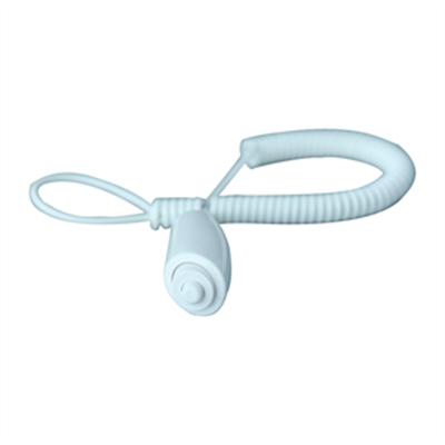
The L08A family offers light and dark shell options. Colour is frequently treated as cosmetic, and in a single-room practice it mostly is. In a site with several rooms, several machines and a shared stock of accessories, colour becomes a control: a switch can be assigned to a room, a machine or a workload, and a misplaced unit becomes visible at a glance. A dark shell in a dimly lit room and a light shell on a dark trolley are also easier to locate. That is a housekeeping advantage, and housekeeping is what keeps a small accessory from disappearing during a busy list.
A parking bracket belongs to the same category of unglamorous advantages. A hand switch that hangs on a stand between examinations keeps its coiled cord off the floor, away from castors and away from cable runs. Cord damage is one of the common failure modes of a wired control, and a bracket is a cheaper answer than a replacement. Where a bracket is supplied, its mounting position is worth including in the installation checklist rather than leaving to chance.
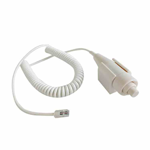
A hand switch is a control accessory, and compatibility is decided at the plug. Exposure inputs across X-ray systems use different connector shapes and different core assignments; the same stage logic can be wired to different pins. The useful advantage in this product line is that the plug and cord construction can be specified against the machine: core count, core function assignment, cord construction and connector type are all items that a written order can fix.
The information needed for that is modest and concrete: the machine make and model, the exposure input documentation, the number of cores and the function of each core, and a photograph of the existing plug. With those items, a matching interface can be built without altering the machine. A claim of universal compatibility is not part of this arrangement; each interface is confirmed individually. This is also why the existing hand switch connector discussion frames the connector as a selection question rather than a yes-or-no answer.
Stage count is the clearest dividing line between the six models, and it is worth reading as a decision table rather than as a feature list.
| Stage structure | What the sequence provides | Where the advantage is real | Boundary to confirm |
|---|---|---|---|
| Single-stage | One press closes the exposure circuit | Fixed geometry, short repeatable sequences | Prepare input is absent from the generator sequence |
| Two-stage | Prepare state held before exposure, release opens both circuits | General radiography, repositioning, veterinary tables | Generator recognises and holds the prepare signal |
| Three-stage | Collimator lamp control added to prepare and exposure | Field-light alignment at the table or stand | Lamp circuit and receiver wiring are present on the machine |
The comparison also makes the limits visible. A three-stage control does not improve image quality, a two-stage control does not shorten an examination, and a single-stage control does not make a room safer. Each one changes where the operator stands and how many decisions sit between a first press and an exposure. A selection made on that basis tends to survive contact with an actual room.
A designation is a short label; a specification sheet is a set of commitments. The following lines are the ones worth having in writing before a hand switch is ordered against a specific machine. None of them is settled by the model name.
| Line to confirm | Why the designation does not settle it | Form of confirmation |
|---|---|---|
| Stage logic and release behaviour | A variant suffix does not state how the prepare state is held | Written stage description on the sheet |
| Connection form and receiver pairing | The same family can be described differently across documents | Corded or cordless stated explicitly, with receiver details where applicable |
| Core count, core function and plug type | Interface is built per machine, not per model name | Wiring diagram plus a photograph of the existing plug |
| Cord construction and working reach | A coiled cord’s relaxed length differs from its extended reach | Construction and reach stated on the sheet |
| Power source, low-battery indication and pairing state | Battery and link behaviour are not encoded in the designation | Written description for cordless configurations |
| Lifetime definition, test basis and warranty handling | Published lifetime figures use differing definitions across sources | Single agreed definition plus the warranty term in writing |
| Shell colour, bracket and mounting position | Colour and bracket options vary within a family | Configuration line on the order |
The same discipline appears in procurement documents for larger equipment; the U-arm and C-arm RFQ discussion uses the same principle that a configuration label has to be resolved into written lines before a quotation is comparable.
The first breakpoint sits between the designation and the configuration. A model name identifies a family; the delivered configuration inside that family is fixed by the order. A second unit with the same designation and a different plug is a different interface, and the difference matters at installation.
The second breakpoint sits between the specification sheet and the product listing. Listing fields such as a rating, a displayed price, a restored-price label or a negotiated-price marker describe a sales presentation. They describe neither the stage logic nor the plug wiring, and they belong outside a technical description. A technical comparison built from listing fields produces a ranking that no room can reproduce.
The third breakpoint sits between the hand switch and the machine. A hand switch does not set exposure parameters, does not determine image quality and does not replace a radiation protection arrangement. It closes circuits in an order defined by the generator. Where a room has a protection plan, an exposure workflow and an equipment acceptance procedure, the hand switch is one control inside that structure, and its specification is confirmed against the machine documentation. Related configuration reading is collected in the portable equipment naming overview and the detector-side room upgrade checklist.
A trailing letter indicates a variant within a configuration family, such as a different trigger mechanism, shell finish or colour option. Version status is stated in the written specification sheet and the order confirmation.
Stage substitution depends on the exposure input design of the generator. Where a prepare state is part of the machine’s exposure sequence, a single-stage control does not provide that state; where the machine exposes on one input, the prepare stage has no function. The machine documentation settles the question.
A cordless model trades cord management for receiver pairing, battery state checks and link verification in the actual room. Fixed installations with short, repeatable workflows often remain simpler with a corded control. The choice follows the room layout and the local protection plan.
The machine make and model, the exposure input documentation, the core count with the function of each core, and a photograph of the existing plug are sufficient to specify a matching interface. Compatibility is confirmed per machine rather than asserted as a general property.
Lifetime figures across available sources use differing definitions for mechanical and electrical endurance. A single agreed definition, its test basis and the warranty handling are more useful than a comparison of unmatched numbers, and they are recorded in writing at the quotation stage.
Written specification sheets, model-to-specification cross-checks, plug and core assignment confirmation, and configuration advice for exposure hand switches.
WhatsApp: +86 19062611512. Email: admin@newheek.cn
Hand switch connector selection for a U-arm | Spare parts and service terms in an equipment plan | Specification checklist discipline for imaging equipment
Author:Newheek-Detector
Tel:+86 19062611512
Email:admin@newheek.cn
Company:Weifang Newheek Electronic Tech Co., Ltd.