an anti-scatter grid is a thin lead-strip plate that sits between the patient and your flat panel detector. It lets the useful primary beam through and absorbs the scattered radiation that would otherwise lay a grey veil over the image. Choose it by matching four things — physical size to your detector’s active area, grid ratio to your working technique, focal distance to your real tube-to-detector distance, and grid density to how much fine detail you need. Get any of the four wrong and the image doesn’t just degrade gracefully: it can fail in ways that look like a broken detector.
Here is a situation every imaging team eventually meets. A detector gets replaced with a shiny new flat panel. The images come back… worse. Grey. Flat. Low contrast. The first suspicion lands on the panel — a warranty claim gets drafted. Then someone notices the old film cassette used to have a grid in front of it, and nobody ever ordered one for the new panel.
The detector was never broken. The scatter was simply unmanaged.
This article is the buyer’s guide to that flat, lead-lined, easy-to-overlook accessory: what the numbers on a grid actually mean, how each one maps to your detector and your room, and the classic failure modes that mimic equipment faults.
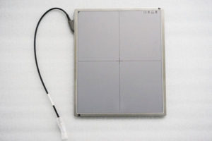
When X-rays pass through a body — a chest, an abdomen, a large dog — most of them pass straight through and reach the detector. But a portion deflects off tissue and arrives at the detector from odd angles, like dust drifting onto a camera lens from the side. That deflected radiation is scatter, and it carries no useful picture information. It just adds a uniform grey fog that washes out the contrast between tissues.
The thicker the body part, the worse the fog. A hand or a wrist barely produces any. A large abdomen or a thick-barreled torso produces plenty. That is why some rooms seem to live happily without a grid for years — until the day a bigger patient arrives.
A grid fixes this mechanically, not digitally. It is an array of thin lead strips separated by radiolucent spacers, angled so that rays travelling straight from the X-ray tube slip through the channels, while rays arriving at an angle — the scatter — slam into a lead wall and are absorbed. The image loses some overall brightness in exchange for contrast, which is exactly the trade you want: the detector can always recover from a slightly darker exposure, but no software can fully undo information drowned in scatter fog.
Grids are made in sizes that follow imaging conventions: 15×20 cm for 5×7-inch films, 23×28 cm for 8×10, 28×33 cm for 10×12, 30×38 cm for 11×14, 33×40 cm for 12×15, 38×38 cm for 14×14, 38×46 cm for 14×17, and 46×46 cm for 17×17. The practical rule is simple: the grid should cover your detector’s active area with a small margin, no more.
Two buying notes worth writing down. First, sizes and parameters are commonly customisable — if your detector sits between standard sizes, ask the supplier rather than forcing the nearest size and losing coverage at one edge. Second, unusual form factors exist for a reason: circular grids (for example Ø242 mm or Ø266 mm versions) are made specifically for 9-inch and 12-inch image intensifier setups, where a rectangular grid simply has no place to sit.

The ratio compares the height of the lead strips to the gap between them. Common choices run from 8:1 up through 10:1, 12:1 and 14:1. A higher ratio rejects scatter more aggressively and delivers cleaner contrast — but it also blocks more of the useful beam, so the exposure technique must rise to compensate, and the grid becomes less forgiving of positioning errors.
The workable way to think about it: low ratios suit thinner body parts and lower-power machines; high ratios suit thick anatomy and rooms that run higher techniques. For general radiography on a fixed machine, mid-to-high ratios are the common territory. For mobile and lower-power work, the gentler end of the range keeps exposures realistic. If you are unsure, tell the supplier the body parts you image and the machine class you run — ratio is a matching decision, not a “bigger is better” decision.
Focused grids have their lead strips angled to converge at one specific distance from the tube. Typical ranges run from 0.7–1.8 m and 0.8–2 m depending on the grid. Use the grid far from its focal distance and the strips themselves begin to absorb the primary beam from the edges inward — the image fades toward the corners as if someone had turned down the brightness on one side.
This is the single most common mismatch we see. Measure the actual tube-to-detector distance in your room — chest work and table work may live at different distances — and pick the grid whose focal range covers it. A grid specified as “F.D 0.8–2 m optional” means you choose where in that range your room sits; it is not a universal pass.
Grid density counts the lead strips per centimetre. Common specifications are 40 L/cm (about 103 lines per inch), 52 L/cm (132 L/In) and 60 L/cm (152 L/In). Finer stripes vanish better into the image — you are less likely to see grid lines on the picture — but they absorb a little more of everything and give the fabricator less room for tolerance. Coarser grids are more forgiving and cheaper to make well.
For most DR work with a flat panel, mid-range densities are the sweet spot. Very fine grids matter most where images are read at high magnification or where the grid sits very close to the image plane. As always with imaging hardware: ask what the default is for your application, and only pay for finer when you have a reason.

Because the grid sits silently in the beam path, its failure modes masquerade as other faults. Four classics worth knowing before you file a warranty claim:
All four are cheaper to fix than a detector replacement. Make “check the grid” step one of any image-quality complaint.
If you tell us your detector model class, the exams you run, and the distances in your room, we will spec the grid to match — including non-standard sizes — rather than sell you the nearest catalogue number.
No. Thin anatomy — extremities, small joints, small pets — produces little scatter, and going gridless keeps the exposure low and the workflow simple. Thicker anatomy — abdomens, chests on larger patients, spines — is where the grid earns its keep. Many departments keep the grid mounted for general work and simply accept the technique adjustment, but the choice is per-exam, not per-room.
Often yes — the grid does not know what is behind it. The things to verify are the physical size against the panel’s active area and the focal distance against your tube geometry. If the old grid matches both, it can migrate to the new panel. If images come back with edge fading after a panel upgrade, the focal distance is the first suspect.
Higher ratios give cleaner contrast on thick anatomy but demand more exposure and tolerate less positioning error. In practice, an 8:1 grid is a forgiving general-purpose choice for lighter work, while 10:1 to 12:1 suits regular thick-body imaging; 14:1 is for rooms that consistently run high techniques and have the output to spare. Pick by your heaviest routine exam, not by the top number on the chart.
Large custom grids — for example oversized panels used in specialized setups — can be awkward to seat without touching the sensitive surface beneath. An integrated hollow handle lets staff place and remove the grid without dragging it across the panel, which protects both the panel surface and the grid alignment.
The same physics applies. Small animals often image without a grid entirely; large dogs, livestock and equine work behave like thick human anatomy and benefit from a grid matched to the technique. Veterinary portable systems in particular should have the grid focal distance checked against the actual working distance, because it is easy to drift from the nominal one.
A grid is one of the few imaging accessories where the cheapest option is almost never the problem — the mismatched option is. Send us your detector’s active area, your working distances, and the anatomy you image, and we will come back with the right size, ratio, focal distance and density, including custom dimensions.
Email: admin@newheek.cn
Phone / WhatsApp: +86 19062611512
Author:Newheek-Detector
Tel:+86 19062611512
Email:admin@newheek.cn
Company:Weifang Newheek Electronic Tech Co., Ltd.